Manual Cutting Cannot Meet Capacity
Hydraulic force and a powered cutting cycle support plate sizes and daily output beyond practical manual or compact electric shearing.
Product Directory
Rectangular Duct Seam Closing Machine
Sheet Metal Notching Machine
Auto Duct Production Line
Round Duct Elbow Making Machine
Duct Beading Machine
Angle Iron Flange Rolling Machine
Spiral Duct Production Line
Language
Hydraulic Sheet Metal Cutting
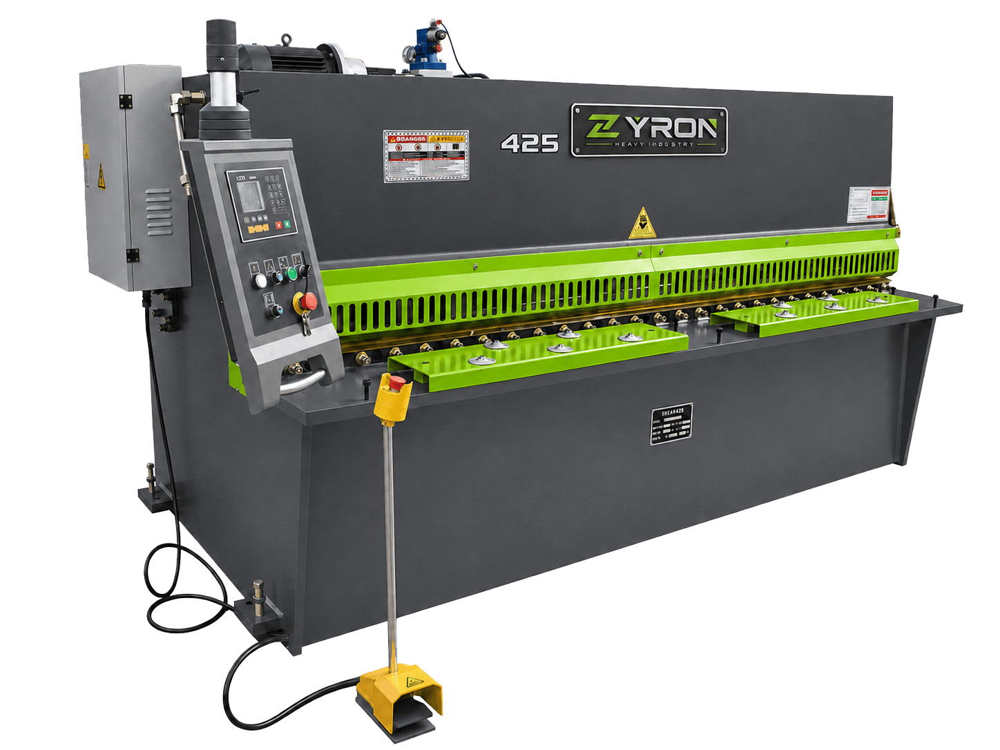
QC12Y/QC12K Hydraulic Sheet Metal Shear for Reliable Plate Cutting
A hydraulic sheet metal shear for straight blanking with an arc-motion blade beam, hydraulic hold-down, adjustable blade clearance and back-gauge positioning across the published 4–40 mm and 2500–8000 mm capacity range.
QC12Y / QC12K Series
Hydraulic Drive
Batch Plate Blanking
Product Overview
A Hydraulic Swing Beam Shearing Machine is a hydraulic metal cutting machine used to produce straight blanks from compatible metal sheet and plate. Hydraulic cylinders move the upper blade beam through a controlled arc while the fixed lower blade provides the opposing cutting edge. The hold-down system stabilizes the workpiece before the cutting stroke, and the back gauge supports repeated blank dimensions.
The source identifies the QC12Y Hydraulic Swing Beam Shear and QC12K Hydraulic Swing Beam Shear as common series and describes an E21S control system for back-gauge positioning. Buyers comparing an NC Hydraulic Swing Beam Shear or CNC Hydraulic Swing Beam Shear should confirm the controller, axes, positioning functions and exact series designation for the selected capacity before ordering.
The published table covers thickness groups from 4 to 40 mm and working lengths from 2500 to 8000 mm under a listed material-strength condition of <=450 kN/cm. These figures do not establish identical capacity for stainless steel, galvanized sheet, aluminum, copper or every grade of carbon steel. Small electric shears suit lighter compact work; a swing beam hydraulic shearing machine is selected when the confirmed material, width or daily output requires greater hydraulic capacity.
Buyer and Production Problems
Hydraulic force and a powered cutting cycle support plate sizes and daily output beyond practical manual or compact electric shearing.
The hydraulic hold-down system secures the sheet before the blade beam moves through the cutting arc.
The back gauge positions the sheet for repeated cutting lengths within the range published for the selected configuration.
Adjustable blade clearance allows the cutting setup to be matched to confirmed material thickness and strength.
Swing Beam Cutting Principle
The operator first confirms the material, positions the sheet against the squaring reference and sets the required blank length through the configured back-gauge control. The hold-down cylinders then clamp the sheet so it does not shift during the cutting stroke.
Hydraulic cylinders drive the upper blade beam through an arc around its pivot. As the upper blade passes the fixed lower blade, the selected blade clearance and shearing angle allow the cut to progress across the working length. This is swing-beam motion—not the near-linear guided blade-holder movement used by a hydraulic guillotine shear.
After the cut, the nitrogen return system described in the source returns the beam for the next cycle. Cutting frequency, angle, back-gauge travel and motor power vary across the original capacity rows and must be selected from the complete workpiece requirement.
Cutting and Positioning Sequence
01
Verify material grade, tensile strength, maximum thickness, working length and required cut quantity.
02
Enter or adjust the repeated blank length using the confirmed manual, NC or CNC control configuration.
03
Use the front support and squaring reference; hydraulic hold-down cylinders secure the sheet before cutting.
04
Hydraulic cylinders move the upper blade beam through its arc past the fixed lower blade.
05
The beam returns and the next sheet is positioned for another confirmed cutting cycle.
Application Scenarios
Prepare straight blanks for bending, rolling, welding and general fabricated components in regular workshop production.
Cut confirmed machine covers, guards, brackets and structural sheet parts before forming and assembly.
Blank compatible gussets, covers and secondary plate components after material strength and capacity review.
Produce repeat panel and enclosure blanks before punching, press-brake bending, joining and assembly.
Cut compatible galvanized blanks for ventilation equipment, duct panels and supporting sheet-metal components.
Prepare straight housing, door, cover and panel blanks for downstream fabrication processes.
Support appropriate non-body structural blanks and workshop components where the confirmed plate specification fits the machine.
Handle varied straight plate-blanking tasks in workshops that need more capacity than a small electric shear.
Material Capability Review
Actual cutting capacity depends on material grade, tensile strength, sheet thickness, working length and machine configuration. The published thickness rows use a listed material-strength condition and must not be copied directly to stainless steel or another material.
A common hydraulic shear application; confirm the grade, tensile strength, thickness and required cutting length.
Select the capacity from the exact carbon-steel grade, strength, plate thickness, width and daily duty.
Do not treat a published mild-steel or <=450 strength value as equal stainless capacity; submit the exact grade for confirmation.
Confirm coating, base-metal grade, tensile strength, thickness and blank length before HVAC or enclosure processing.
Provide alloy, temper, thickness, working length and cut-quality requirement for machine selection.
Confirm copper grade, material condition, thickness and required cutting length before configuration approval.
Other grades require engineering review of strength, ductility, thickness, working length and blade setup.
Core Machine Systems
The machine combines a welded frame, hydraulic drive, arc-motion blade beam and practical positioning systems. Final control and capacity must match the selected configuration.
Hydraulic cylinders provide the force that moves the swing beam through the cutting stroke.
The upper blade holder follows a swinging path relative to the fixed lower blade.
Clearance is adjusted for the confirmed material thickness and strength to support cutting quality and blade life.
Hold-down cylinders secure the plate before the blade beam begins the cutting action.
The source table lists 20–600, 20–750 or 20–1000 mm travel depending on capacity configuration.
The source references E21S back-gauge control; confirm whether the ordered machine is QC12Y or QC12K and which functions are included.
The source describes nitrogen-cylinder return for stable movement after the cutting stroke.
Machine Structure
All-steel welded frame
Provides the structural base for hydraulic cutting and plate support.
Hydraulic drive system
Supplies controlled pressure to the cylinders that move the blade beam.
Swinging upper blade beam
Moves through an arc relative to the fixed lower blade during the cutting stroke.
Upper and lower blades
Create the shearing action with clearance selected for the confirmed material.
Hydraulic hold-down cylinders
Clamp the plate before the blade enters the cutting stroke.
Back-gauge system
Positions the plate for repeated blank dimensions within the published travel range.
Controller and electrical system
Manage the configured back-gauge and operating functions; final controller scope requires order confirmation.
Original Product Data
The HTML table preserves all 40 original capacity rows and their published values. NEEDS PRODUCT DATA VERIFICATION: the source identifies QC12Y/QC12K series and an E21S control system but does not state the exact QC12Y/QC12K model prefix and controller mapping for each row. Confirm designation, control, material capacity and final configuration before quotation.
| Model | CuttingThickness(mm) | CuttingWidth(mm) | CuttingAngle(deg) | MaterialStrength(kN/cm) | BackgaugeTravel(mm) | CuttingTimes(T/min) | Main MotorPower(kW) | Overall DimensionsL x W x H(mm) |
|---|---|---|---|---|---|---|---|---|
| 4 x 2500 | 4 | 2500 | 1 deg30 min | <=450 | 20-600 | 16 | 4 | 3040 x 1610 x 1620 |
| 4 x 3200 | 4 | 3200 | 1 deg30 min | <=450 | 20-600 | 14 | 5.5 | 3840 x 1610 x 1620 |
| 4 x 4000 | 4 | 4000 | 1 deg30 min | <=450 | 20-600 | 10 | 5.5 | 4600 x 1700 x 1700 |
| 4 x 6000 | 4 | 6000 | 1 deg30 min | <=450 | 20-600 | 8 | 7.5 | 6460 x 2100 x 3200 |
| 6 x 2500 | 6 | 2500 | 1 deg30 min | <=450 | 20-600 | 14 | 7.5 | 3040 x 1610 x 1620 |
| 6 x 3200 | 6 | 3200 | 1 deg30 min | <=450 | 20-600 | 12 | 7.5 | 3840 x 1610 x 1620 |
| 6 x 4000 | 6 | 4000 | 1 deg30 min | <=450 | 20-600 | 8 | 7.5 | 4620 x 1750 x 1700 |
| 6 x 5000 | 6 | 5000 | 1 deg30 min | <=450 | 20-600 | 6 | 11 | 5400 x 1800 x 1900 |
| 6 x 6000 | 6 | 6000 | 1 deg30 min | <=450 | 20-600 | 5 | 11 | 6480 x 2100 x 2300 |
| 8 x 2500 | 8 | 2500 | 1 deg30 min | <=450 | 20-600 | 10 | 11 | 3040 x 1700 x 1700 |
| 8 x 3200 | 8 | 3200 | 1 deg30 min | <=450 | 20-600 | 8 | 11 | 3860 x 1700 x 1700 |
| 8 x 4000 | 8 | 4000 | 1 deg30 min | <=450 | 20-600 | 8 | 11 | 4640 x 1700 x 1700 |
| 8 x 5000 | 8 | 5000 | 1 deg30 min | <=450 | 20-600 | 8 | 11 | 5400 x 2100 x 2000 |
| 8 x 6000 | 8 | 6000 | 1 deg30 min | <=450 | 20-600 | 8 | 11 | 6480 x 2100 x 2350 |
| 10 x 2500 | 10 | 2500 | 2 deg | <=450 | 20-600 | 9 | 15 | 3040 x 1700 x 1700 |
| 10 x 3200 | 10 | 3200 | 2 deg | <=450 | 20-600 | 9 | 15 | 3860 x 1700 x 1700 |
| 10 x 4000 | 10 | 4000 | 2 deg | <=450 | 20-600 | 8 | 15 | 4650 x 2100 x 2000 |
| 10 x 6000 | 10 | 6000 | 2 deg | <=450 | 20-1000 | 5 | 15 | 6500 x 2100 x 2300 |
| 12 x 2500 | 12 | 2500 | 2 deg | <=450 | 20-600 | 9 | 15 | 3140 x 2150 x 2000 |
| 12 x 3200 | 12 | 3200 | 2 deg | <=450 | 20-600 | 9 | 15 | 3880 x 2150 x 2000 |
| 12 x 4000 | 12 | 4000 | 2 deg | <=450 | 20-600 | 8 | 18.5 | 4680 x 2150 x 2000 |
| 12 x 5000 | 12 | 5000 | 2 deg | <=450 | 20-750 | 6 | 18.5 | 5900 x 2150 x 2000 |
| 12 x 6000 | 12 | 6000 | 2 deg | <=450 | 20-750 | 5 | 18.5 | 6900 x 2600 x 2700 |
| 12 x 8000 | 12 | 8000 | 2 deg | <=450 | 20-1000 | 5 | 18.5 | 9000 x 3500 x 3500 |
| 16 x 2500 | 16 | 2500 | 2 deg30 min | <=450 | 20-600 | 9 | 22 | 3140 x 2150 x 2000 |
| 16 x 3200 | 16 | 3200 | 2 deg30 min | <=450 | 20-600 | 8 | 22 | 3880 x 2150 x 2000 |
| 16 x 4000 | 16 | 4000 | 2 deg30 min | <=450 | 20-600 | 8 | 22 | 4650 x 2150 x 2200 |
| 16 x 5000 | 16 | 5000 | 2 deg30 min | <=450 | 20-750 | 6 | 22 | 5900 x 2600 x 2700 |
| 16 x 6000 | 16 | 6000 | 2 deg30 min | <=450 | 20-750 | 5 | 22 | 6900 x 2700 x 2700 |
| 16 x 8000 | 16 | 8000 | 2 deg30 min | <=450 | 20-1000 | 5 | 22 | 9000 x 3500 x 3500 |
| 20 x 2500 | 20 | 2500 | 3 deg | <=450 | 20-1000 | 8 | 22 | 3440 x 2300 x 2500 |
| 20 x 3200 | 20 | 3200 | 3 deg | <=450 | 20-1000 | 8 | 22 | 4150 x 2350 x 2700 |
| 20 x 4000 | 20 | 4000 | 3 deg | <=450 | 20-1000 | 5 | 22 | 4850 x 2600 x 2700 |
| 20 x 6000 | 20 | 6000 | 3 deg | <=450 | 20-1000 | 4 | 30 | 6700 x 3000 x 3000 |
| 25 x 2500 | 25 | 2500 | 3 deg | <=450 | 20-1000 | 8 | 37 | 3200 x 2700 x 2900 |
| 25 x 3200 | 25 | 3200 | 3 deg | <=450 | 20-1000 | 5 | 37 | 4200 x 2700 x 2900 |
| 30 x 2500 | 30 | 2500 | 3 deg | <=450 | 20-1000 | 4 | 37 | 3300 x 2900 x 3000 |
| 30 x 3200 | 30 | 3200 | 3 deg30 min | <=450 | 20-1000 | 4 | 40 | 4200 x 2900 x 3200 |
| 40 x 2500 | 40 | 2500 | 4 deg | <=450 | 20-1000 | 3 | 55 | 3200 x 3300 x 3000 |
| 40 x 3200 | 40 | 3200 | 4 deg | <=450 | 20-1000 | 3 | 55 | 4300 x 3300 x 3200 |
Published Capacity Range
The source table names capacity rows by thickness × cutting width. These are searchable capacity configurations, not permission to add an unverified QC12Y or QC12K prefix to every row.
01
Published 4 x 2500, 4 x 3200, 4 x 4000 and 4 x 6000 configurations cover 2500–6000 mm working lengths.
02
Published 6 x 2500 through 6 x 6000 and 8 x 2500 through 8 x 6000 configurations include 2500, 3200, 4000, 5000 and 6000 mm lengths.
03
Published groups run from 10 x 2500 to 10 x 6000 and from 12 x 2500 to 12 x 8000, including 2500mm, 3200mm and 4000mm Hydraulic Swing Beam Shear capacity choices.
04
The source includes 16 x 2500 through 16 x 8000 and 20 x 2500 through 20 x 6000 configurations for confirmed material-strength conditions.
05
The source ends with 25 x 2500, 25 x 3200, 30 x 2500, 30 x 3200, 40 x 2500 and 40 x 3200. Engineering confirmation is essential at these capacities.
Machine Selection Comparison
Both are hydraulic shearing machines. Select by blade movement, material, thickness, required cutting result, production volume, maintenance capability and budget rather than assuming either design is always better.
| Selection factor | Hydraulic Swing Beam Shear | Hydraulic Guillotine Shear |
|---|---|---|
| Blade movement | Upper blade beam follows an arc around its pivot | Upper blade holder follows near-linear guided movement |
| Machine structure | Practical swing-beam arrangement for economical hydraulic cutting | Rigid guided guillotine arrangement for more demanding work |
| Typical cutting application | Routine sheet and plate blanking in general fabrication | Higher-specification plate cutting where guidance and rigidity are priorities |
| Thickness and accuracy decision | Choose when the confirmed work fits the published swing-beam capacity and tolerance requirement | Consider when material strength, thickness or cutting requirement justifies guillotine guidance |
| Maintenance and investment | Simpler mechanism and value-focused general fabrication profile | More demanding guidance and generally higher configuration level |
| Selection input | Material, thickness, length, daily cuts, tolerance and budget | The same inputs, with extra emphasis on demanding plate and accuracy requirements |
Engineering Selection Guide
Start with the workpiece and production requirement. The table below identifies when the current swing-beam range is a candidate and when a guillotine or another cutting process should be reviewed.
| Selection factor | Select Swing Beam for Review | Consider Guillotine or Another Process |
|---|---|---|
| Material and strength | The exact grade and tensile strength fit a confirmed swing-beam capacity | Higher-strength material or special edge requirements need a different configuration |
| Thickness and length | Both values match one original 40-row configuration | Required values exceed the table or need different blade-holder behavior |
| Production volume | Routine batch blanking suits the confirmed cutting frequency and handling plan | Higher automation, feeding or demanding continuous duty changes the machine choice |
| Control and positioning | Confirmed NC/CNC controller and back gauge meet repeat-size requirements | More axes, tolerance control or automated handling are required |
Production Workflow
The hydraulic swing beam shear prepares straight blanks. Press-brake bending, plate rolling, welding, joining and assembly remain separate downstream processes selected from the finished part requirement.
Step 1
Plate Cutting
Step 2
Press-Brake Bending
Step 3
Plate Rolling
Step 4
Welding or Joining
Step 5
Assembly
Manufacturing and Supply Review
ZYRON supports configuration review, manufacturing coordination, inspection and export preparation for buyers comparing a Hydraulic Swing Beam Shear Manufacturer, Hydraulic Swing Beam Shear Supplier, Hydraulic Shearing Machine Manufacturer, Hydraulic Sheet Metal Shear Manufacturer or QC12Y Hydraulic Swing Beam Shear Manufacturer.
Review the all-steel welded frame, structural parts, mounting positions and visible joints before final assembly.
Check hydraulic connections, cylinders, valves, motor, electrical cabinet, controls and configured safety functions.
Review blade installation, clearance setup, hold-down action, back-gauge movement and sample cutting where appropriate.
Confirm specification, voltage, accessories, documentation, export packing and technical handover before shipment.
Buyer Questions
It is a hydraulic sheet metal shearing machine whose upper blade beam swings through an arc relative to a fixed lower blade. It produces straight blanks before bending, rolling, welding or assembly.
The operator positions the plate against the back gauge, the hold-down system clamps it, and hydraulic cylinders move the upper blade beam through an arc past the fixed lower blade. Selected blade clearance and angle support the confirmed cutting condition.
QC12Y is identified in the source as a common hydraulic swing-beam series. The project also names QC12K and an E21S control system, but exact model-prefix and controller mapping must be confirmed for the selected capacity row.
Possible materials include mild steel, carbon steel, stainless steel, galvanized sheet, aluminum, copper and other metal plate. Actual capacity depends on grade, tensile strength, thickness, working length and configuration.
A confirmed stainless grade may be cut within an approved machine capacity, but the published thickness table cannot be applied automatically. Submit the stainless grade, tensile strength, thickness and working length for written confirmation.
The original table lists nominal groups from 4 to 40 mm under a published material-strength condition of <=450 kN/cm. These are not universal limits for every material, and each thickness must be checked with the required cutting length.
The source table includes 2500, 3200, 4000, 5000, 6000 and 8000 mm working lengths, but not every thickness is available at every length. Choose an exact row and confirm the machine designation before quotation.
A swing beam shear moves the upper blade in an arc and is often selected for economical routine hydraulic blanking. A guillotine shear uses near-linear guided blade-holder movement and may be considered for more demanding plate, rigidity or cutting requirements.
Both designations are named in the source, but the current project does not provide a verified row-by-row definition or controller mapping. NEEDS PRODUCT DATA VERIFICATION: confirm the exact series, controller, axes and back-gauge functions in the quotation.
Start with material grade and strength, maximum thickness, cutting length, daily cuts, required tolerance, controller, back gauge, handling method, budget and downstream process. Then compare a confirmed swing-beam row with guillotine and other cutting options.
Provide material and grade, tensile strength, normal and maximum thickness, maximum cutting length, required blank sizes, cuts per day, tolerance, preferred controller, back-gauge requirement, voltage, options and destination.
Hydraulic Swing Beam Shear Price depends on cutting thickness, cutting length, controller, back gauge, hydraulic configuration, optional equipment, voltage, destination and shipping requirements. Request a confirmed quotation when comparing a Hydraulic Swing Beam Shearing Machine for Sale.
Related Sheet Metal Equipment
Manufacturer Quotation
Send material grade and strength, maximum thickness, cutting length, required accuracy, daily cuts, controller, back gauge, hydraulic configuration, optional equipment, voltage, destination and shipping requirements. ZYRON will review the correct hydraulic shearing machine before quotation.