01
Plate positioning can slow the first pass
Clamping the plate between the top and bottom rolls supports alignment before the side rolls begin the approved forming sequence.
Product Directory
Rectangular Duct Seam Closing Machine
Sheet Metal Notching Machine
Auto Duct Production Line
Round Duct Elbow Making Machine
Duct Beading Machine
Angle Iron Flange Rolling Machine
Spiral Duct Production Line
Language
Four-roll hydraulic plate forming for tank shells, cylinders, pressure vessels and heavy fabrication.
A hydraulic four-roll plate rolling machine designed to clamp the plate between the top and bottom rolls while the side rolls support pre-bending and forming. Share your material, thickness, width, target diameter and workpiece drawing so the actual capacity, control and handling configuration can be confirmed.
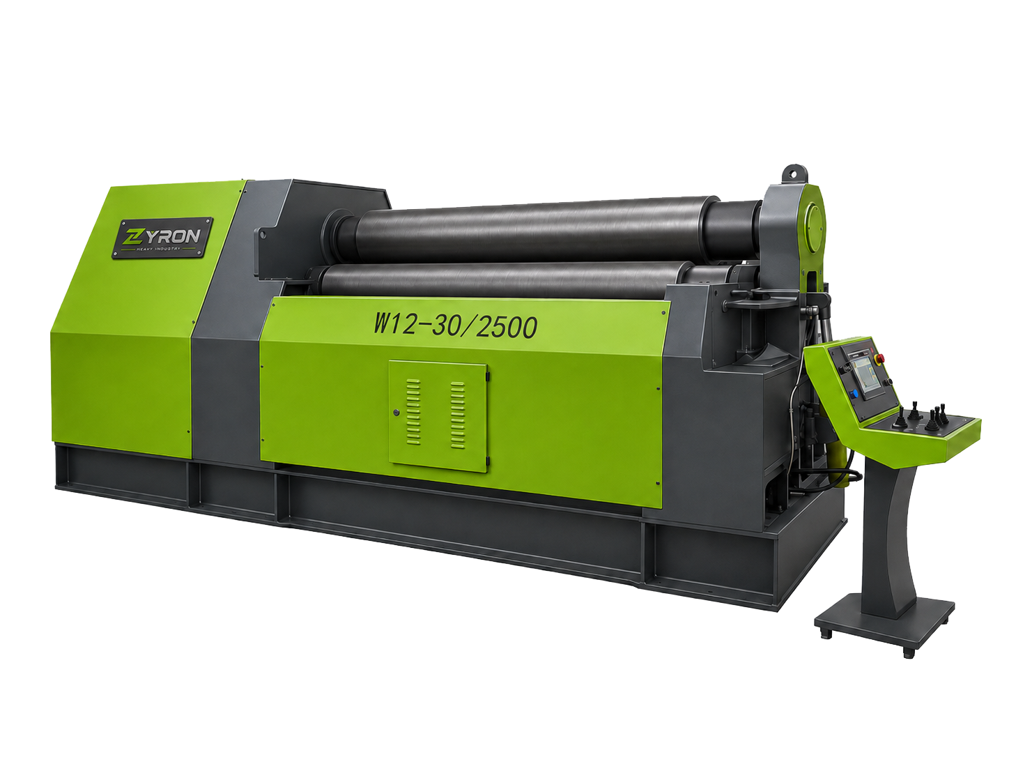
Hydraulic four-roll platform
Final capacity and control subject to confirmation
Rolling problems
The machine creates value when clamping, edge preparation, rolling passes, inspection and material handling are planned around the actual shell.
Clamping the plate between the top and bottom rolls supports alignment before the side rolls begin the approved forming sequence.
An engineered four-roll pre-bending sequence can reduce the unformed portion at compatible plate ends before closing and welding.
Hydraulic movement supports controlled roll positioning, but capacity must be selected from material strength, width, thickness and diameter together.
Configured position feedback and NC or CNC functions can organize repeated passes while measurement and inspection remain essential.
Side support, overhead lifting, feeding and discharge options should follow the real blank and completed shell weight.
Four-roll solutions
Select the machine from the workpiece envelope, material strength, production quantity and handling plan.
Combine clamping, edge pre-bending, rolling, checking and seam preparation in one controlled fabrication route.
Configure the rolls, hydraulic system, support devices and workshop flow around the actual plate and workpiece.
Match the blank, control sequence, cone arrangement and inspection method to the requested geometry.
Real applications
These real photographs show representative industries and fabricated parts. Machine suitability is confirmed from your material and drawings.
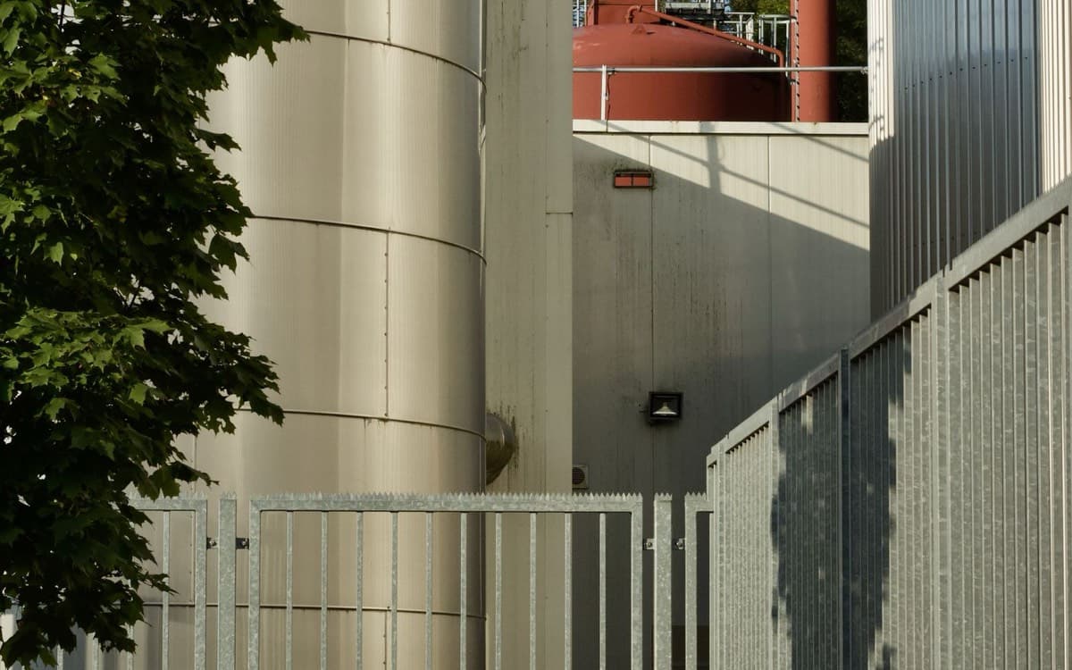
Real process-vessel installations represent cylindrical shell work that requires material review, edge preparation, controlled rolling and qualified downstream joining.
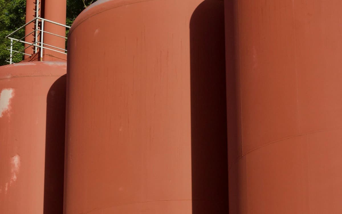
Tank farms illustrate multi-course shell production where stable plate clamping, diameter checks and an organized welding route support repeat fabrication.
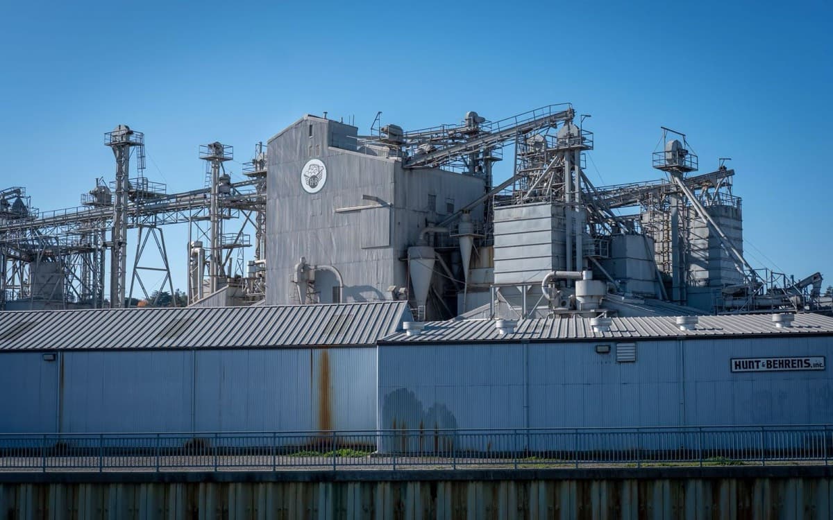
Industrial process plants show the cylindrical vessels, pipework and structural context surrounding rolled boiler and process-equipment shells.

Wind-energy structures use large cylindrical or tapered sections whose plate strength, weight, rolling route and material handling must be engineered together.
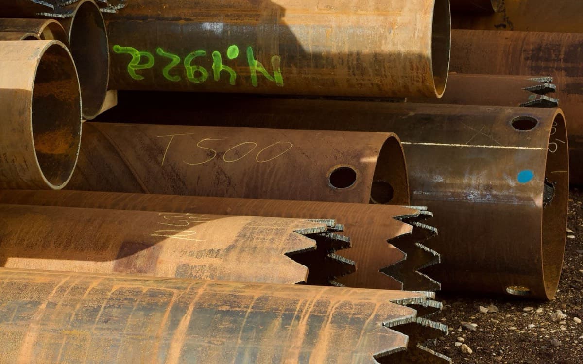
Large pipe sections move from plate forming to longitudinal welding, calibration and connection preparation in a controlled fabrication sequence.
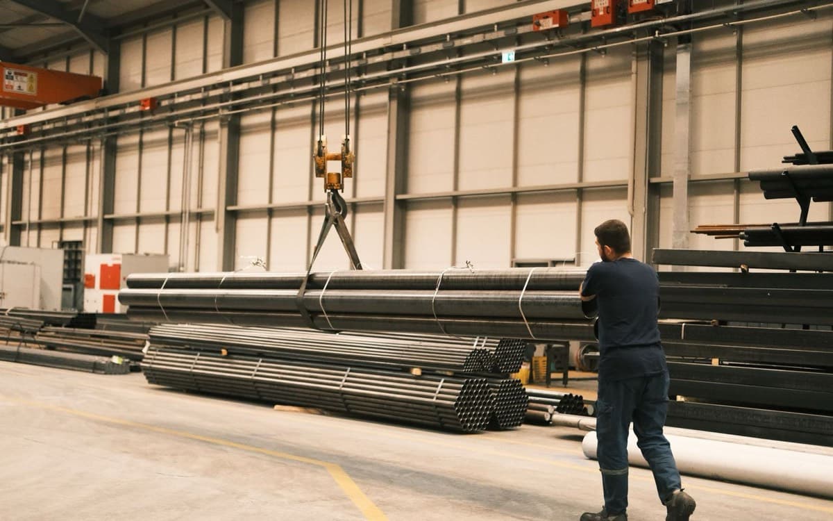
Heavy cylindrical workpieces make plate weight, support, overhead handling, discharge clearance and foundation planning part of machine selection.
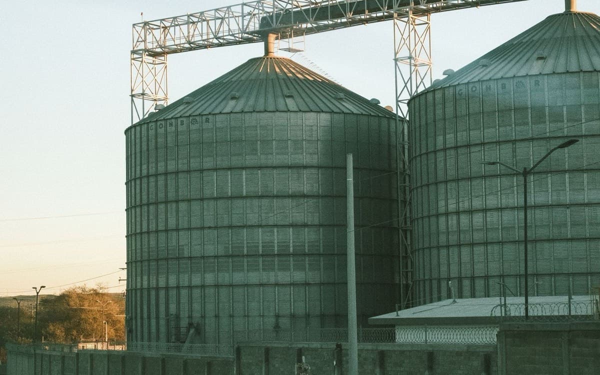
Tapered industrial structures illustrate compatible cone work that depends on blank geometry, roll movement, cone arrangement and the approved forming sequence.

Curved metal panels represent open-arc forming where radius, springback, surface protection and segment matching need drawing-led control.
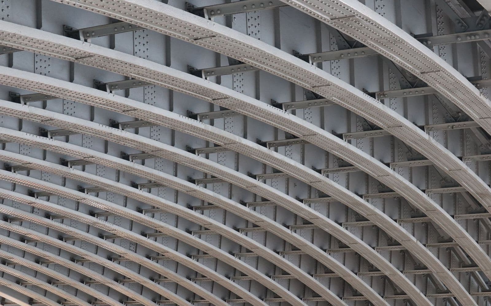
Curved structural steel components require the forming capacity, profile geometry and connection details to be checked against fabrication drawings.
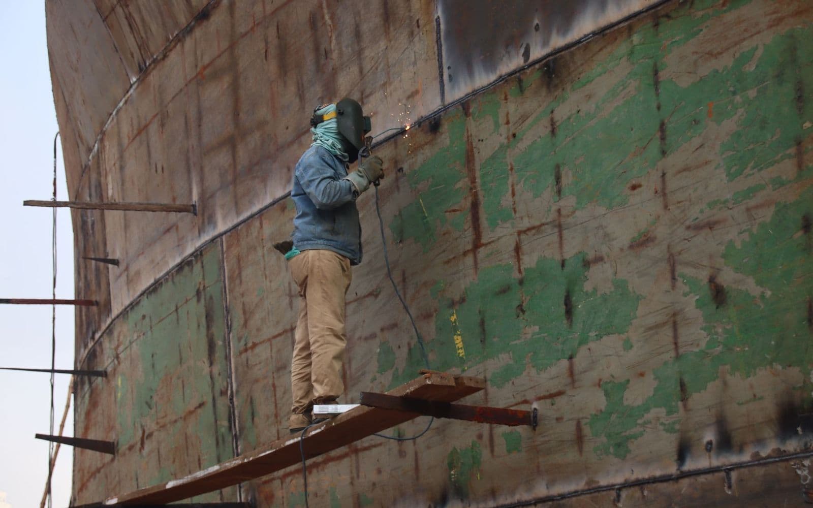
Shipyard fabrication connects curved plate forming with fitting, welding, inspection and large-assembly handling around the hull production plan.
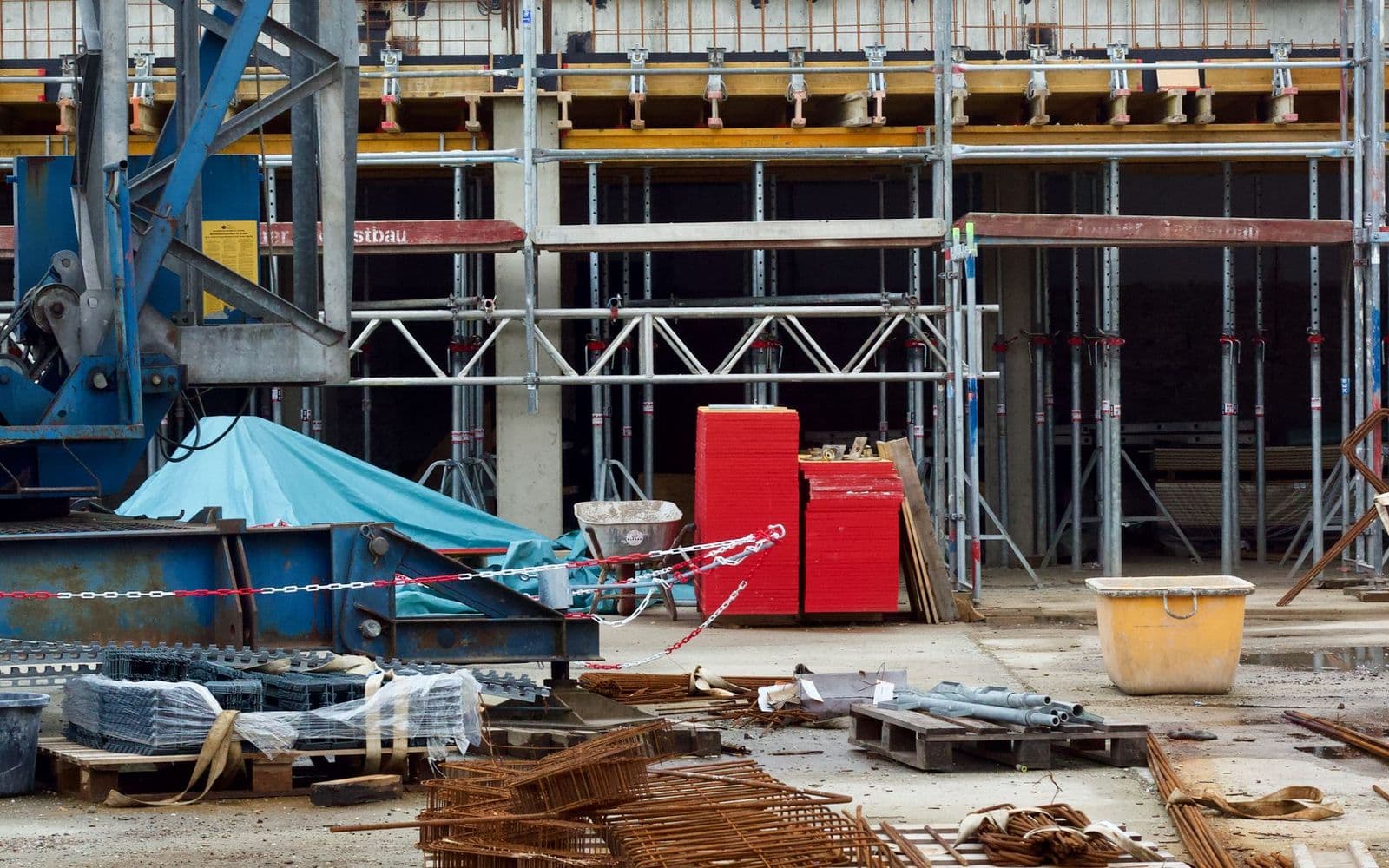
Heavy-equipment environments represent formed housings, covers and curved components that require material-specific capacity confirmation.
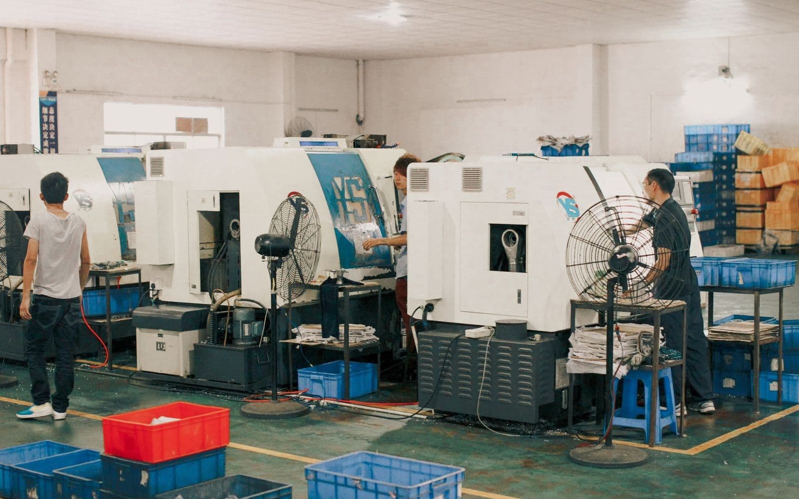
A real factory floor shows why loading access, trained operators and coordinated movement between forming and downstream stations matter.
Materials
Suitable thickness depends on strength, width, diameter, pre-bending demand, roll geometry and the selected machine configuration.
Confirm grade, yield strength, thickness, width and target diameter.
Confirm strength, plate condition, forming direction and pre-bending demand.
Confirm grade, finish protection, strength and springback.
Provide the complete material specification for an engineering capacity review.
Confirm alloy, temper, surface sensitivity and expected springback.
Confirm coating condition, target radius and downstream seam process.
Confirm workpiece weight, support, lifting, foundation and discharge route.
Formed workpieces
Final quality depends on the material, blank, target geometry, pre-bending process, roll positions and operating setup.
Complete round shells prepared for joining, calibration or assembly.
Shell courses matched to tank diameter and seam requirements.
Engineering-led cylindrical sections for qualified downstream fabrication.
Rolled sections prepared for longitudinal joining and inspection.
Tapered blanks formed with a confirmed machine arrangement and sequence.
Open-radius segments for structures, guards and industrial assemblies.
Drawing-defined panels where surface and radius are considered together.
Curved covers and shells for machinery and industrial equipment.
Four-roll process
The forming sequence belongs inside a complete route that includes blank preparation, controlled clamping, dimensional checks and downstream joining.
01
Cut the blank, prepare edges and confirm rolling direction and seam allowance.
02
Load the plate and align it with compatible feeding or workshop lifting equipment.
03
Clamp the plate between the top and bottom rolls according to the selected configuration.
04
Move the relevant side roll through the approved first-edge sequence.
05
Coordinate the working rolls through the required passes to form the shell.
06
Complete the opposite edge sequence without changing the overall setup when compatible.
07
Measure diameter, roundness or radius and correct the process when required.
08
Unload safely, then continue to welding, calibration or assembly.
Four-roll design
The existing product photograph remains the source of truth for visible structure. Final movement axes, drive and discharge details follow the confirmed machine.
Works with the bottom roll to establish plate contact and contributes to the forming geometry.
Supports hydraulic clamping and controlled plate feeding in the selected machine design.
Move to support pre-bending, rolling passes and geometry correction according to the approved sequence.
Provides controlled roll positioning; drive layout and movement axes depend on the confirmed model.
Supports rolling force and alignment for the specified plate range and workshop duty.
A configured opening or support arrangement assists discharge of compatible completed shells.
Hydraulic system
Hydraulic layout, pressure range, synchronization, filtration and cooling are confirmed against the proposed duty cycle.
Hydraulic actuators position the configured rolls through clamping, pre-bending and rolling steps.
Pressure indication and protective functions depend on the selected hydraulic and control package.
Position feedback can coordinate both sides of a moving roll when included in the configuration.
Reservoir, filtration, hoses, seals and cooling requirements are confirmed for the proposed duty cycle.
Pre-bending and clamping
The plate is held between the top and bottom rolls while the side rolls are positioned for the leading edge, main rolling passes and trailing edge. This can streamline plate handling and shell-closing preparation, but the achievable result depends on material strength, thickness, width, roll geometry, target diameter and the approved pass sequence.
Control options
Controller, position feedback, stored programs and cycle complexity must be confirmed before quotation.
Operator-led roll movement and checking for flexible, lower-volume workshop production.
Digital position feedback and stored settings depend on the confirmed controller and sensors.
Programmed multi-step roll positioning may support compatible repeat shell work.
Recipe storage and recall are available only when included with the selected control system.
Remote support or production-data interfaces require separate confirmation before quotation.
Material handling
Handling equipment must match plate dimensions, plate weight, completed-shell geometry, daily quantity and workshop access.
An optional powered table can support repeat blanks when matched to plate dimensions and weight.
Configured supports help manage large-diameter shells and reduce uncontrolled movement.
Tall or large shells may require an overhead support system or workshop crane plan.
The opening and support arrangement must match the finished shell diameter and weight.
A compatible ejector, crane or fixture can move the workpiece to its next station.
Machine advantages
Top-and-bottom roll contact supports controlled positioning before and during forming.
Compatible leading and trailing edge pre-bending can be completed in the same overall setup.
Controlled roll movement supports heavy-duty plate applications after engineering selection.
Multiple geometries can be evaluated from the material and workpiece drawing.
Manual hydraulic, NC and CNC-oriented configurations serve different production needs.
Feeding, side support, overhead support and discharge can be planned as one cell.
Position feedback and stored steps can support repeat production when included.
Connects with cutting, welding, calibration, flanging and finishing processes.
Machine comparison
Each structure serves a different workload. Final selection follows the workpiece, output, handling needs and desired control level.
| Selection point | Semi-automatic three-roll | Fully automatic three-roll | Hydraulic four-roll |
|---|---|---|---|
| Roller structure | Three working rolls | Three working rolls | Top, bottom and two side rolls |
| Plate clamping | Depends on structure and setup | Depends on confirmed structure | Between top and bottom rolls |
| Pre-bending route | Operator and structure dependent | Programmed option by configuration | Integrated side-roll sequence by configuration |
| Control focus | Assisted operation | Automatic three-roll cycle | Hydraulic clamping and coordinated roll positioning |
| Repeat production | Flexible small and medium batches | CNC-oriented batch work | Repeat shell work with selected NC or CNC control |
| Material handling | Operator-led and optional support | Optional automation package | Stable clamping plus configured support options |
| Configuration investment | Balanced | Higher automation level | Higher structural and hydraulic integration |
| Recommended use | General cylinder, arc and varied work | Automatic batch cylinders and compatible cones | Tank shells, cylinders and selected heavy plate work |
Complete production route
The rolling machine becomes most productive when blank preparation, handling, welding, checking and finishing are designed as one cell.
Prepare compatible straight-cut plate blanks.
Prepare shaped blanks, holes and reference features.
Prepare selected large-format or thick plate blanks.
Clamp, pre-bend and roll the approved shell sequence.
Join the longitudinal seam to the specified procedure.
Support compatible circumferential welding and assembly.
Form compatible shell edges for the next assembly stage.
Check and correct geometry after joining when required.
Continue to grinding, blasting, coating or polishing.
Configuration guide
Send these inputs with a workpiece drawing so the recommendation starts from the real process rather than a generic model name.
Grade, yield strength, temper, coating and surface condition.
Nominal thickness, working width and expected range.
Cut length, seam allowance and blank geometry.
Required cylinder diameter and minimum rolling diameter.
Cylinder, cone, arc, tank shell or custom geometry.
Required edge condition and acceptable straight portion.
Daily volume, batch size and changeover frequency.
Manual hydraulic, NC or CNC-oriented operation.
Plate weight, table, side support and overhead support.
Drop end, ejector, lifting fixture and crane interface.
Voltage, floor, space, access and lifting equipment.
Cutting, welding, flanging, calibration and finishing route.
Include the drawing, material, production quantity and handling plan.
Technical specifications
The four existing project values remain unchanged. Every added field requires confirmation for the selected machine.
| Model | Rolling Capacity | Roll Structure | Operation Mode | Workpiece | Rolling Lengthmm | Plate Thicknessmm | Pre-bending Thicknessmm | Minimum Rolling Diametermm | Top Roll Diametermm | Bottom Roll Diametermm | Side Roll Diametermm | Control System | Hydraulic System | Roll Drive | Feeding Method | Unloading Method | Motor PowerkW | Rolling Speedm/min | VoltageV | Machine Sizemm | Machine Weightkg | Application |
|---|---|---|---|---|---|---|---|---|---|---|---|---|---|---|---|---|---|---|---|---|---|---|
| Hydraulic Four-Roll Plate Rolling Machine | Selected by plate thickness, width, material, and minimum diameter | Two-roll, three-roll, or four-roll construction | Electric, semi-automatic, fully automatic, or hydraulic | Cylinders, arcs, cones, and curved sheet components | Customizable / Please confirm with our sales engineer | Customizable / Please confirm with our sales engineer | Customizable / Please confirm with our sales engineer | Customizable / Please confirm with our sales engineer | Customizable / Please confirm with our sales engineer | Customizable / Please confirm with our sales engineer | Customizable / Please confirm with our sales engineer | Customizable / Please confirm with our sales engineer | Customizable / Please confirm with our sales engineer | Customizable / Please confirm with our sales engineer | Customizable / Please confirm with our sales engineer | Customizable / Please confirm with our sales engineer | Customizable / Please confirm with our sales engineer | Customizable / Please confirm with our sales engineer | Customizable / Please confirm with our sales engineer | Customizable / Please confirm with our sales engineer | Customizable / Please confirm with our sales engineer | Customizable / Please confirm with our sales engineer |
Final specifications depend on plate material, strength, thickness, rolling length, target diameter, pre-bending requirement, control system, supports and machine configuration.
Workshop preparation
Prepare stable power, floor capacity, anchoring and service access for the confirmed machine.
Verify blank size, rolling direction, edge condition and seam allowance before production.
Plan plate approach, feeding, crane access and controlled placement before installation.
Reconfirm stainless, high-strength or heavy plate for every production range.
Large shells may require side support, overhead lifting, a rotator or a dedicated fixture.
Follow the delivered requirements for oil, filtration, seals, hoses, cooling and inspection.
Use trained personnel, delivered guards and instructions, and applicable local workshop rules.
Related equipment
For CNC-oriented repeat cylinder and compatible cone work.
For flexible assisted rolling and varied workshop production.
For compatible thin-sheet cylinder forming.
For straight plate blank preparation.
For productive sheet cutting and shaped blanks.
For compatible large-format plate preparation.
FAQ
It is a plate forming machine with top, bottom and two side rolls. A selected hydraulic system moves the configured rolls for plate clamping, edge pre-bending, cylinder rolling and correction.
The plate is generally clamped between the top and bottom rolls, then the side rolls are positioned through leading-edge pre-bending, main rolling passes and trailing-edge pre-bending. The exact sequence depends on the design and workpiece.
A four-roll design adds a second side roll and emphasizes clamping and controlled positioning in one setup. Three-roll machines remain versatile for many cylinder, arc and compatible cone jobs. Selection should follow the workpiece and production plan.
Common candidates include compatible carbon steel, stainless steel, galvanized plate, aluminum and selected alloy steel. Capacity depends on material strength, thickness, width, target diameter and configuration.
It can form compatible cylinders and tank shells after the material, width, thickness, diameter, edge condition and downstream joining route are confirmed.
Compatible cone sections may be formed when the tapered blank, cone dimensions, roll arrangement, attachment and process sequence are reviewed together.
Manual hydraulic, NC and CNC-oriented controls may be configured. Position feedback, program memory and automatic sequences depend on the selected controller and machine build.
Compatible stainless steel can be rolled after its grade, strength, thickness, width, finish requirements, springback and target diameter are reviewed.
Feeding tables, supports, drop-end discharge, ejectors and lifting integration are configuration options selected from plate size, shell weight, production quantity and workshop layout.
Provide material, strength, thickness, width, blank length, target and minimum diameter, workpiece drawing, pre-bending need, output, control level, voltage and handling plan.
It can form compatible vessel shells, but the machine, plate preparation, rolling, welding and inspection route must satisfy the applicable project and regulatory requirements.
Send the workpiece drawing, material, thickness, width, blank length, target diameter, daily quantity, voltage, control preference, feeding and unloading needs, connected equipment and destination.
Send your plate material, thickness, width, target diameter, drawing and handling requirements. We will recommend a suitable hydraulic four-roll plate rolling machine configuration for your workshop.